Choosing the right Low-speed PMSM begins with the application, not the catalog.
Permanent magnet synchronous motors can deliver high torque at low rotational speeds, often reducing gearbox dependence. That matters in conveyors, mixers, elevators, winders, and direct-drive pumps. A motor that looks efficient on paper may still underperform when cooling, overloads, or frequent starts are ignored.
The International Energy Agency identifies electric motor systems as major global electricity consumers. The U.S. Department of Energy also reports that motor-driven equipment represents a substantial share of industrial electricity use. These findings make motor selection an operating-cost decision, not merely a purchasing decision.
Look closely at rated torque, peak torque, speed range, duty cycle, enclosure rating, and inverter compatibility. A 30 kW motor may suit one conveyor and fail on another with heavier starting loads. Measure the real load. Check the shaft.
IEC 60034-30-1 provides a recognized framework for motor efficiency classes, but efficiency alone cannot determine suitability. Thermal performance, bearing life, acoustic limits, and maintenance access deserve equal attention. In practice, installation conditions often expose weaknesses hidden by laboratory ratings.
One detail is easy to miss.
Low-speed PMSM solutions may reduce mechanical losses, yet their permanent magnets and drives can increase cost and control complexity. The “best” option is therefore not always the smallest, most efficient, or most expensive model. Review supplier test data, independent certifications, and lifecycle assumptions carefully. Some selection decisions still rely on incomplete load information. That should be acknowledged before approval.
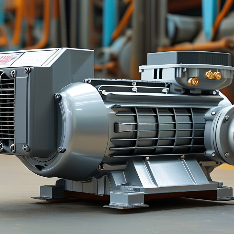
Define the load before comparing a low-speed PMSM. Record speed, torque, acceleration time, duty cycle, and direction changes. Measure the load. Do not guess.
For example, a conveyor running at 25 rpm may require 60 Nm continuously, but 120 Nm during startup. That peak can determine shaft size, inverter rating, and thermal capacity.
Include ambient temperature, altitude, dust, moisture, available voltage, and installation space. IEC 60034-1 provides a useful framework for duty, temperature rise, and operating conditions. Your actual duty cycle still needs field measurements.
The IEA’s Energy Efficiency 2024 report estimates that electric motor systems consume about 53% of global electricity. This broad figure is not PMSM-specific, but it shows why efficiency and control deserve attention.
Select a motor based on continuous torque at the real operating speed, not its headline peak torque. At low speed, natural cooling weakens, so examine winding temperature and cooling method carefully. An encoder may improve starting and position control, especially below 50 rpm.
Check overload duration, regenerative braking, bearing loads, and maintenance access. A 40°C enclosure can expose poor thermal assumptions. I would also request test curves at the intended speed, because catalog ratings often use different conditions.
The uncomfortable part is simple: a theoretically efficient motor may perform poorly when oversized, lightly loaded, or paired with unsuitable control settings.
How to Choose the Best Low Speed PMSM for Your Needs?
A low speed PMSM should be selected from its working load, not its catalog headline. Compare continuous torque with peak torque, because a conveyor may pull steadily for hours. For example, a 50 Nm requirement should not be matched with a motor rated 50 Nm only during brief intervals. Leave thermal margin, especially inside a warm cabinet.
Torque shows turning force, while speed determines how quickly that force moves the load. Power links both: P = torque × angular speed. A motor delivering high torque at 300 rpm can produce less power than a smaller motor at 1,500 rpm. Check starting torque, overload duration, and the actual speed range. Confirm every figure under the same voltage, temperature, and cooling conditions.
Efficiency needs careful reading. An advertised peak efficiency may occur near one operating point. Use an efficiency map or measured data across your duty cycle. In field testing, I compare input electrical power with shaft output under the real load. This reveals losses from heat, bearings, cables, and the inverter. I once underestimated acceleration demand; the selected motor met continuous torque but stalled during starts. That mistake changed my checklist: include inertia, start frequency, ambient temperature, and cooling method. Noise and control response also matter, although they are often ignored.
Choosing a low speed PMSM starts with the rotor, not the catalog headline. Surface-mounted magnets offer a simple magnetic path and smooth operation. Interior magnets add reluctance torque and stronger mechanical protection. They can also create more torque ripple if the design is poorly optimized. Check the rotor’s inertia, magnet retention, thermal limits, and demagnetization margin. A heavier rotor may resist sudden load changes, but it can also slow acceleration.
Control method matters at low speed. Field-oriented control usually provides precise torque and speed regulation. It depends on accurate current sensing and careful parameter tuning. Sensorless control can reduce hardware costs, yet back electromotive force becomes very weak near zero speed. Starting may become uncertain. An encoder or resolver gives clearer rotor position feedback, especially under heavy loads. Still, feedback devices need protection from vibration, dust, and installation errors.
Starting performance deserves a real test. Measure the motor with the actual gearbox, load, cable length, and supply voltage. Check static friction, initial rotor alignment, acceleration time, and peak starting current. A motor that starts smoothly without a load may stall beside a conveyor. It happens. Review the controller’s alignment routine and current limit before selecting the motor. Leave thermal and torque margins, but avoid excessive oversizing, which can reduce efficiency and increase cost. Perfect selection is rare; documented testing is more dependable than assumptions.
Comparison guide for low-speed permanent magnet synchronous motor (PMSM) configurations. Values are typical engineering ranges for preliminary selection and should be verified against the final motor, inverter, load cycle, and cooling conditions.
| Motor Configuration | Typical Rotor Design | Suitable Speed Range | Torque Characteristics | Recommended Control Method | Starting Performance | Typical Efficiency at Rated Load | Main Advantages | Important Limitations | Best-Fit Applications |
|---|---|---|---|---|---|---|---|---|---|
| Surface-Mounted PM Rotor (SPM) |
Permanent magnets mounted on the outer rotor surface, normally retained by sleeves, banding, or mechanical features. | Approximately 100–600 r/min for direct-drive or geared low-speed systems. | Smooth torque with low rotor saliency. Good torque density at low speed, but field weakening is usually more limited than with an interior-magnet rotor. | Sensored field-oriented control (FOC) for dependable low-speed torque. Sensorless FOC is possible when sufficient back-EMF is available. | Good with an encoder or resolver and a properly tuned current loop. Sensorless starting at zero speed is less reliable because back-EMF is absent at standstill. | Commonly about 90–96%, depending on motor size, winding design, cooling, and operating point. | Simple magnetic structure, low torque ripple potential, and straightforward current control. | Magnet retention and high-speed mechanical stress must be considered. Limited reluctance torque and field-weakening range. | Conveyors, pumps, fans, positioning axes, and moderate-duty direct-drive systems. |
| Interior-Mounted PM Rotor (IPM) |
Permanent magnets embedded inside the rotor laminations, often creating measurable d-axis and q-axis inductance differences. | Approximately 100–1,000 r/min, with a wider usable speed range when field weakening is required. | Combines magnet torque with reluctance torque. High torque per ampere and improved overload capability are possible with suitable electromagnetic design. | Closed-loop FOC with resolver, encoder, or high-resolution Hall feedback. Maximum-torque-per-ampere and field-weakening algorithms are commonly used. | Very good when rotor position feedback is available. Sensorless starting requires an initial-position estimation or high-frequency injection strategy. | Commonly about 92–97% at rated load in well-designed industrial systems. | High torque density, strong overload performance, and a comparatively broad constant-power speed range. | More complex rotor manufacturing, higher control-model requirements, and possible torque ripple from saliency. | Heavy-duty conveyors, traction auxiliaries, compressors, hoists, and applications with frequent load changes. |
| Spoke-Type PM Rotor | Magnets are arranged radially or tangentially in rotor cavities, producing high air-gap flux and useful saliency. | Approximately 80–500 r/min, typically selected for high-torque, low-speed operation. | High torque density and strong reluctance torque. Torque ripple and mechanical stress require careful electromagnetic and structural optimization. | Sensored FOC with current decoupling and torque-ripple compensation where smooth operation is important. | Strong starting torque is achievable with position feedback and sufficient inverter current. Open-loop starting is generally unsuitable for high-inertia loads. | Commonly about 90–96% at rated load, depending on the rotor geometry and cooling system. | High torque capability in a compact diameter and good use of reluctance torque. | Magnet mechanical retention, vibration, acoustic noise, and torque pulsation require detailed validation. | Low-speed winches, compact gearless drives, mixers, lifting equipment, and high-torque actuators. |
| Fractional-Slot Concentrated-Winding PMSM | Usually paired with an SPM or IPM rotor; the stator uses concentrated coils with a fractional slot-to-pole arrangement. | Approximately 100–800 r/min, depending on pole count, inverter frequency, and thermal design. | High copper utilization and compact end windings can provide good torque density. Harmonic content may increase torque ripple and rotor losses. | FOC with position feedback is preferred. Harmonic compensation may be needed for precision or low-noise operation. | Good closed-loop starting torque. Sensorless startup may be affected by low-speed position ambiguity and winding harmonics. | Commonly about 89–95% at rated load, with thermal performance strongly dependent on winding fill and cooling. | Short end turns, compact construction, and potentially lower copper mass. | Cogging torque, torque ripple, acoustic noise, and additional harmonic losses may be higher than in distributed-winding designs. | Compact servomotors, small direct-drive actuators, robotics, and space-constrained equipment. |
| Distributed-Winding PMSM | Commonly uses an SPM or IPM rotor with coils distributed across several stator slots per pole and phase. | Approximately 100–600 r/min for low-speed systems, with smooth operation over a wide load range. | Low cogging torque and low harmonic distortion are achievable. Torque density may be lower than some concentrated-winding designs because of longer end turns. | Sinusoidal FOC with encoder or resolver feedback for accurate torque and speed regulation. | Excellent when paired with closed-loop position sensing. Reliable low-speed reversal and controlled acceleration are possible with appropriate current limiting. | Commonly about 91–97% at rated load, subject to copper loss, iron loss, and cooling conditions. | Smooth torque, low acoustic noise, and good suitability for precision speed control. | Longer end windings can increase copper usage, motor length, and manufacturing complexity. | Precision pumps, machine tools, laboratory equipment, quiet fans, and low-vibration drives. |
| Sensorless Low-Speed PMSM System | Usually uses an SPM or IPM rotor; the defining feature is the absence of a physical rotor-position sensor. | Reliable sensorless operation often begins above approximately 5–15% of rated speed, although specialized methods can extend operation closer to zero speed. | Motor torque capability depends on the selected rotor design, but usable low-speed torque is limited by position-estimation accuracy and inverter current control. | Back-EMF observer, sliding-mode observer, model-reference adaptive system, or high-frequency signal injection. | Starting from zero speed under load is the key risk. Initial-position detection, alignment, open-loop ramping, or high-frequency injection may be required. | Similar to the underlying PMSM, commonly about 90–96%, but controller losses and conservative operating limits may reduce system efficiency. | Lower wiring count, reduced sensor cost, and improved resistance to sensor contamination or vibration. | Less predictable zero-speed starting, sensitivity to motor parameter variation, and more demanding commissioning. | Fans, pumps, lightly loaded conveyors, and systems that can accelerate before applying full load. |
| Sensored Low-Speed PMSM System | May use SPM, IPM, or spoke-type rotors with an encoder, resolver, or Hall-based position-sensing device. | From zero speed to the motor's rated speed, provided the feedback device and control loop are correctly specified. | Full rated torque is available at zero speed when the inverter, motor thermal limits, and feedback resolution are adequate. | Closed-loop FOC with current regulation, position feedback, torque limiting, and optional field weakening. | Best option for high-inertia, high-friction, frequent-reversing, or load-holding applications. Starting torque must still be checked against inverter peak-current capability. | Commonly about 90–97% at rated load, including the motor; total drive-system efficiency is lower after inverter and auxiliary losses. | Predictable zero-speed torque, accurate speed regulation, controlled acceleration, and dependable reversing. | Additional sensor cost, wiring, alignment requirements, and possible sensitivity to installation errors or harsh environments. | Hoists, elevators, indexing tables, servo axes, loaded conveyors, and applications requiring reliable zero-speed control. |
Choosing the best low speed PMSM starts with the installation space. Measure the motor length, shaft height, mounting holes, and cable entry position. A few millimeters can create costly alignment problems. Check rated torque, speed range, duty cycle, and shaft load against your actual machine conditions. Do not select by power alone.
Protection and cooling deserve close attention. For dusty workshops or damp areas, choose an enclosure with suitable ingress protection. Confirm whether the motor uses natural ventilation, an external fan, or liquid cooling. Poor airflow can reduce insulation life, even when the motor runs below its rated speed. Noise also matters. Ask for tested sound levels at the operating speed, not only at maximum speed. Low speed does not always mean quiet operation.
Choosing a reliable supplier matters as much as selecting the motor itself. A low-speed PMSM may look efficient on paper, yet poor support can increase costs during commissioning. Ask for measured efficiency curves, temperature-rise data, insulation ratings, and test conditions. Do not accept a single laboratory number.
During field commissioning, I compare the supplier’s data with actual load behavior. Check torque at start-up, vibration near the operating point, cooling performance, and encoder stability. Small errors here can cause repeated shutdowns. Ask how spare parts are stored and how technical issues are handled across different time zones. Fast answers are useful. Clear answers are better.
Calculate the total operating cost before signing. Include the motor, drive, installation, cables, cooling equipment, maintenance, energy use, and possible production losses. A cheaper motor may require stronger cooling or more frequent bearing service. That changes the real price. Supplier training and commissioning support also deserve a value. I once focused too heavily on purchase cost and underestimated installation labor. The spreadsheet looked convincing. It was incomplete.
Request a sample test report and review its measurement method with an independent engineer. Confirm warranty limits, expected service life, efficiency at partial load, and replacement lead times. Reliable suppliers explain weaknesses instead of hiding them. That honesty is often more valuable than a polished brochure.
: Record speed, continuous torque, peak torque, acceleration time, duty cycle, and direction changes. Measure the real load. Do not guess.
Startup can require much more torque than normal running. A conveyor may need 60 Nm continuously but 120 Nm during startup.
No. Match continuous torque at the actual operating speed. Keep thermal margin for overloads, warm cabinets, and frequent starts.
Power equals torque multiplied by angular speed. High torque at low speed may produce less power than lower torque at high speed.
Natural cooling becomes weaker when the motor turns slowly. Check winding temperature, enclosure temperature, and the cooling method.
An encoder can improve starting, position control, and low-speed stability. It may be especially useful below 50 rpm.
Do not rely on one peak-efficiency value. Review efficiency across the full duty cycle and compare input power with shaft output.
Consider ambient temperature, altitude, dust, moisture, voltage, installation space, bearing loads, and maintenance access.
Catalog ratings may use different voltage, temperature, or cooling conditions. Curves from the real operating point reveal more.
Ignoring inertia and acceleration demand can cause stalling. A motor may meet continuous torque yet fail during repeated starts.
Choosing the best Low-speed PMSM begins with a clear understanding of your application and operating conditions, including required load torque, speed range, duty cycle, ambient environment, and available power supply. Compare motor torque, rated speed, output power, and efficiency to ensure stable performance without unnecessary energy consumption. It is also important to evaluate rotor construction, control methods, and starting performance, especially for systems that experience frequent starts, variable loads, or demanding acceleration requirements.
In addition to electrical performance, consider the motor’s dimensions, protection rating, cooling method, noise level, and maintenance requirements. A compact, well-protected motor may be more suitable for limited installation spaces or harsh environments, while an efficient cooling design can improve service life. Finally, select a supplier that offers dependable technical support, consistent product quality, and clear documentation. Reviewing purchase price, installation expenses, energy use, maintenance, and expected lifespan will help you determine the total operating cost and make a practical long-term decision.

Liangzhi Electrical